This post aims to provide IoT enthusiasts & makers with the basic information to connect any kind of devices to FIWARE Lab so they (or any other developer) may use the information provided to build useful Apps. With devices we really mean anything: sensors, actuators, wearables, robots, drones… The only limit is your imagination!
FIWARE Lab ecosystem is rich in context information from devices placed at connected Smartcities so our developers can integrate them into their Apps or products. The following picture depicts the main cities with public devices available today. And these are only the first ones, many are coming up soon!
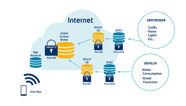
Developers may easily consume this information via the secured Global instance of Orion Context Broker. Find how to do it in the Annex of this tutorial.
However, we believe we can boost our ecosystem if you contribute by connecting your own devices, being home-made, commercial or whatever.
What you will get in turn? You will be able to easily create useful Apps, services or just plain dashboards thanks to the extensive catalogue of FIWARE GEs. Moreover, you may share it with other developers, that may make that work for you.
STEP 1: Understanding the options to connect devices to FIWARE Lab
There are basically 3 ways or scenarios to connect devices to FIWARE Lab:
A) ContextConsumer: If you are connecting a device that just consumes information from FIWARE Lab, such as a smartwatch, smartglasses, a drone taking decisions on FIWARE Lab resources conditions, etc. you just need to connect to the Global instance of Orion ContextBroker as described in this manual. Additionally, there is a practical example in this article annex at the end.
On the contrary, if you are connecting devices that provide information to FIWARE Lab, and possibly receive commands, then you have two options depending on the scale and scope of your solution:
B) Large IoT deployments, especially if devices are autonomous 2G/3G sensors or gateways. In this case we do recommend using our carrier-grade solution “DCA-IDAS Backend Device Management GE”. We do recommend this approach even when you are starting with a limited number of devices
C) Limited IoT deployments: In this case you may skip DCA component and feed a ContextBroker directly just as any other ContextProvider would do, providing that you can develop the NGSI REST operations in your device or a close-by IoT Gateway.
Scenario (A) is not really specific to IoT as your devices will be consuming Context Information, as any other Application would do.
For options (B) and (C) the best way to get started is to use a Raspberry PI as IoT Gateway and our opensource Figway tool for RaspberryPI. You may connect commercial devices to the Raspberry PI (Z-wave is explained in this article) or even Arduino-based ones connected to the PI GPIO. There is a nice tutorial for that here.
In you are not using a Raspberry Pi at all, you can still use this post to understand the basics, analyze the commands source code (C/C++) and other files so you can easily adapt the code and philosophy to your own platform.
STEP 2: Installing & Configuring Figway software in a Raspberry PI
Access our GIT repository at: https://github.com/telefonicaid/fiware-figway/
Get a Raspberry PI with the latest Raspbian OS installed and clone our software by running:
> git clone git://github.com/telefonicaid/fiware-figway/
Change to “figway/sources” folder and compile with the following command:
> cd figway/sources
> g++ -o registerDevice registerDevice.cpp clientSocketHttp6-test.cpp clientSocketHttp6-test.h g++ -o sendObservations sendObservations.cpp clientSocketHttp6-test.cpp clientSocketHttp6-test.h g++ -o addObservation addObservation.cpp
>
> g++ -o fizway_switchd fizway_switchd.cpp
> cd ..
If you are connecting a Z-wave network of devices move on now to “STEP 6: Using Fizway tools to connect a whole Z-wave Network”, otherwise keep on reading.
The relevant files for you at this point are:
- registerDevice: it enables you to register a device in a M2M platform (via SensorML or NGSI9/10). You are expected to provide a DEVICE_ID and a DEVICE_TYPE. Devices need to be registered in the M2M platform prior to send/receive any data.
- addObservation: once you collect an observation from a sensor you can store this in the RPI with this command.
- sendObservations: once you have collected all observations from a device you can send all them in a single packet with this command. It will generate an error if no observations are added or not all observation types have been updated.
You can safely ignore fizway* files by now as these ones are mainly related to Z-wave networks discussed in STEP 6, although you will need also some of them for receiving commands in STEP 5.
Before executing these commands you may need to check and edit the figway “Config” file. An example “Config.example” file is provided.
All the commands above provide help on usage if executed with no arguments.
Let’s have a look to the Config file:
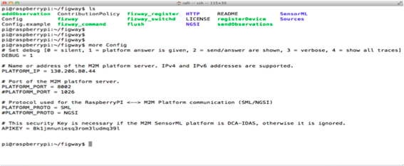
It is indeed quite self-explanatory. This is the way you have to update it:
•DEBUG =1 . Leave it to 1 unless you are debugging.
•PLATFORM_IP = 130.206.80.44 for Scenario B or C.
•PLATFORM_PORT = 8002 for Scenario B or
– PLATFORM_PORT = for Scenario C.
• PLATFORM_PROTO = SML to connect to DCA (Scenario B) or
– PLATFORM_PROTO = NGSI to connect to ContextBroker
• APIKEY = 6rs973ggt1q04gp7d9p0nho1bl. Only needed for Scenario B as it is ignored if Scenario C is selected above.
STEP 3: Using Figway commands to register your devices
Prior to send observations or receive any commands from FIWARE Lab, all your devices need to be registered. Registration is an idempotent operation, you may repeat this process to update the stored information or if you are not sure it is done before.
The command used for registry has the following syntax:
>./registerDevice [DEVICE_ID] [DEVICE_TYPE]
- [DEVICE_ID] is a 4-digit identifier of your device. This number has to be unique for each connected Raspberry PI domain. The easiest is to do a numbering plan for your devices like this one: “0001”, “0002”, “0003”, etc.
- [DEVICE_TYPE] is the type of device that you are using and it has to match with one of those available at the SensorML folder (Scenario B) or NGSI folder (Scenario C). The reason for this is that in the process of registration that template will be modified and sent to our IoT backend.
As a practical exercise, we will assume the following scenario:
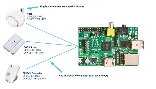
Our example exercise holds three devices:
- a “4IN1 sensor”: measuring Presence, Illuminance, Temperature & Humidity.
- a “Door sensor”: sending Open/Close Status updates.
- A “Controlled-Switch”, sending power consumption, its current status (ON/OFF) and able to receive ON/OFF commands.
Note that if you understand this proposed scenario you will be able to connect any other kind of home-made or commercial devices.
Note as well that we do not care now how Devices are actually connected to the Raspberry PI, because you may use any kind of solution: from direct wiring to the RaspberryPI GPIO or any radio/cable technology with the correspondent dongle & drivers in the Raspberry PI, such as: X-10, X-10 RF, Zigbee, Z-wave (this particular one is explained later in this post).
Step 3.1: Edit the Template files for Devices Registration
- For Scenario B, you will see all the device templates we need at SensorML/ folder and you will modify them this way:
- Register_4IN1. Edit this file and:
– Replace all “HACKSANTANDER” strings with the actual name of the service we are using “OpenIoT” (important note: it is case-sensitive). - Register_DOOR. Similarly, edit this file and:
– Replace “HACKSANTANDER” strings with “OpenIoT”. - Register_SWITCH. As this is an actuator we need to configure not only the service we are using but also the IP address and port to receive commands. Therefore, edit this file and:
– Replace “HACKSANTANDER” strings with “OpenIoT”.
– Replace “http://194.73.233.51:7777” with “http://[IP]:10000” where IP is the public IP address of your Raspberry PI.
For Scenario C, proceed exactly the same as for Scenario B but:
- working in NGSI/ folder.
- replacing “UKCAMPUSPARTY” strings with “OpenIoT” .
- and, for the SWITCH, replacing “http://1.0.0.1:8888” with “http://[IP]:10000” where IP is the public IP address of your Raspberry PI.
Important note: If you are in a NAT-ed environment (the PI has a private IPv4):
- For the [IP] field in the files above use the public IPv4 address of your router-NAT. Do not forget to configure that router-NAT to forward TCP 10000 port to the private IPv4 address of your PI and Port 10000.
- Note that Figway is IPv6-ready so if your ISP is providing that to you, you may use the PI IPv6 addresses to receive commands instead. This way you’ll avoid configuring a router-NAT. Just be sure your v6-firewall is accepting incoming TCP connections to port 10000 for the PI v6 address.
Step 3.2: Registering your devices in FIWARE Lab IoT Backend
Now that you have identified and edited the Register templates for your specific [DEVICE_TYPE], you just need to register devices by executing:
>./registerDevice 0001 4IN1
>./registerDevice 0002 DOOR
>./registerDevice 0001 SWITCH
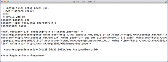
For each command above, you will see something similar to this in case of success: (This is a snapshot for Scenario B, Scenario C is a different 200 OK response)
Step3.3: And what if I want to register different type of devices?
The only thing you need is to define a new type of Sensor template, say “MYSENSOR”, and create the correspondent registration template file:
- If it is, for instance, just sending Temperature just copy “Register_4IN1” file to “Register_MYSENSOR” and edit this file removing the XML sections for other observations (Move, Illuminance and Humidity).
- If your device is just sending any other numeric or string observation the better copy “Register_DOOR” to “Register_MYSENSOR” and modify it accordingly.
- If your device is receiving commands too, just add the XML section describing the URL for commands http:[IP]:[PORT] taking “REGISTER_SWITCH” as a working example.
For all these modifications above, remember to create the files at SensorML/ folder for Scenario B or at NGSI/ one for Scenario C.
STEP 4: Using Figway commands to send your devices’ observations
Whenever you want to send an observation of a device to FIWARE Lab IoT backend, you need to make it in two steps:
- Add observations to a temporary file (addObservation command)
- Send all the observations in the temporary file (sendObservation command)
The reason for this approach is to allow multisensing devices (like the 4IN1) to store and/or send different measurements at different times or from different software components or functions.
Step 4.1: Edit the Template files for Devices Observations
Similarly to the registration process you need to identify each template and properly modify it. The difference here is that you will have as many files as Observations types per each [DEVICE_TYPE]. In our example scenario:
For Scenario B, you will see all the device observation templates we need at SensorML/ folder and you will modify them this way:
- 4IN1 related Files: Observation_4IN1_MOV, Observation_4IN1_TEM, Observation_4IN1_LUM, Observation_4IN1_HUM
– Replace “HACKSANTANDER” strings with “OpenIoT”.
- DOOR related files: Observation_Door_STAT.
– Replace “HACKSANTANDER” strings with “OpenIoT”.
- SWITCH related files: Observation_Switch_POW, Observation_SWITCH_STAT.
– Replace “HACKSANTANDER” strings with “OpenIoT”.
For Scenario C, proceed exactly the same as for Scenario B but:
- working in NGSI/ folder.
- replacing “UKCAMPUSPARTY” strings with “OpenIoT” .
Step 4.2: Sending your devices’ obervations to FIWARE Lab IoT Backend
The correct syntax of the two needed commands is as follows:
>./addObservation [DEVICE_ID] [DEVICE_TYPE] [OBS_TYPE] [OBS_VALUE]
>./sendObservation [DEVICE_ID] [DEVICE_TYPE] [OBS_TYPE]
Let’s make the exercise for the 4IN1 in two different ways:
- Your code collects all environments measurements every 10 minutes and wants to send them to the backend:
>./addObservation 0001 4IN1 TEM [Temperature]
>./addObservation 0001 4IN1 HUM [Humidity]
>./addObservation 0001 4IN1 LUM [Illuminance]
>./sendObservations 0001 4IN1 TEM
>./sendObservations 0001 4IN1 HUM
>./sendObservations 0001 4IN1 LUM
- Your code wants to report MOVE Status whenever the 4IN1 triggers that event by detecting a person in the room:
>./addObservation 0001 4IN1 MOV MOVE
>./sendObservations 0001 4IN1 MOV
- Your code wants to report QUIET Status whenever the 4IN1 triggers that state (normally some timeout after the MOVE was detected).
>./addObservation 0001 4IN1 MOV QUIET
>./sendObservations 0001 4IN1 MOV
Step 4.3: And what if I want to use different type of devices?
Let’s assume you have a sensor type “MY_SENSOR” that you have already registered with its “Registration_MYSENSOR” template file as indicated in the previous paragraphs.
Now you need to identify how many observation types your devices is managing.
Let’s assume it manages Temperature and Humidity. Then you would need to create the template files “Observation_MYSENSOR_TEM” and “Observation_MYSENSOR_HUM” that you may take from “Observation_4IN1_TEM” and “Observation_4IN1_HUM” respectively.
If your sensor would be providing some different numeric or string status, you might create the file “Observation_MYSENSOR_STAT” taking “Observation_DOOR_STAT” as a reference.
If your device is receiving commands you do not need to modify any specific field for that in any observation template file.
Remember to create observation templates in SensorML/ folder if you are working with Scenario B or in NGSI/ folder if in Scenario C,
STEP 5: enabling devices to receive Commands
In our scenario there is a SWITCH device that is suitable to receive ON/OFF commands. Keep on reading this section only if you have devices that will receive commands from the backend or any other place in the Internet.
Step 5.1: Configuring fizway_switchd tool to receive commands.
There is command that will launch a TCP server for you, parse commands if any and deliver the result to another program called “fizway
Its correct syntax is:
>./fizway_switchd [Device_ID] [DEVICE_TYPE] [Server_Port]
Where [Device_ID] and [DEVICE_TYPE] are those one you used for that device registration and [Server_Port] is the TCP port to listen at for commands in the Raspberry PI. This port must match the one provided in the registration template URL string http://[IP]:[PORT].
In our specific example, we just need to launch it this way:
>./fizway_switchd 0003 SWITCH 10000
Note that you may launch as many servers (at different ports) as many command-capable devices you have.
Step 5.2: test your devices correctly receive commands
We can test to turn our switch on by connecting to our command server at the Raspberry PI with a regular telnet client (from the PI or any other machine, we assume PI address to be 192.168.1.50) and type:
> telnet 192.168.1.50 10000
< FIZCOMMAND 255 >
Or, to turn the switch off with:
> telnet 192.168.1.50 10000
< FIZCOMMAND 0 >
The following section explains how to make that fizway tools and your code cooperate to effectively hit your device.
Step 5.3: And what if I want to use different type of actuator devices?
Commands sent to devices have the form “FIZCOMMAND [COMMAND] ”, where [COMMAND] can be any string with no spaces nor “>” symbol in between as long as those characters are used to determine its end.
Example commands and their result are:
- “FIZCOMMAND ON “: valid. Command argument will be “ON”
- “FIZCOMMAND OFF”: Not valid as there is no space at the end.
- “<FIZCOMMAND ON>” Valid as there is a “>” symbol at the end.
- “FIZCOMMAND THIS_IS_A_TEST_OF_STRING “: valid.
- “<FIZCOMMAND THIS_IS_A_TEST_OF_STRING>“: valid.
- “FIZCOMMAND THIS IS A TEST OF STRING “: Valid, but only “THIS” will be sent as argument of the command.
Once you send a command to this server and the parsing is valid, it will automatically invoke “fizway_command” bash script this way:
>./fizway_command [DEVICE_NUMBER] [DEVICE_TYPE] [COMMAND_VALUE]
Where the [COMMAND_VALUE] is the command that you sent to the server.
This way, you only need to incorporate in “fizway_command” script the actions you want to perform for your specific device when receiving certain commands. You may also replace the whole script by any other component providing that you keep its name and invocation syntax so the server “fizway_switchd” will correctly call it.
A working example is shown later in this post for the Z-WAVE scenario.
Step 5.4: Send commands to your devices from our IoT Backend
At this time, this possibility is only working for scenario B (DCA). If you are dealing with scenario C you will need to send the commands yourself to the command server in the Raspberry PI as previously explained in section 5.2.
For scenario B, you just need to use the Administration API of DCA-IDAS that we show in the following capture:
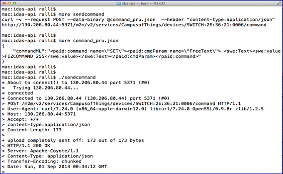
Note: differently to this screenshot, the ADMIN API is publicly offered at port 80 and it is secured with a keyrock PEP-Proxy as all other public GEs in FIWARE Lab. Check this article annex to learn how to obtain and use an access token prior to try the example above.
STEP 6: Using Fizway tools to connect a whole Z-wave Network
All the previous steps assume you are connecting any kind of devices. However, we have made life easier for the case you are connecting a Z-wave network of devices by providing also the code to manage them as shown in the following picture:
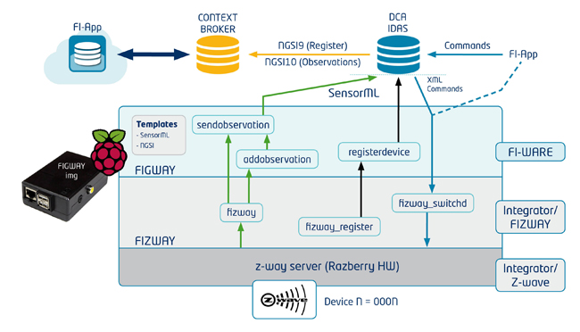
The picture draws the case of scenario B, but actually scenario C would be similar but sending information directly to the ContextBroker (bypassing DCA-IDAS). In scenario C, commands would be only sent directly to the RaspberryPI (dotted blue line).
The good news for Z-WAVE devices is that you only need to follow the following steps:
1. Build your Z-WAVE network as you usually do. For testing we used a RaspberryPI and a Razberry Z-wave GPIO dongle with its included software.
2. Install and Configure Figway tool as described in “STEP 2: Installing & Configuring Figway software in a Raspberry PI”.
3. Edit the file “fizway_register” and “fizway” files
a. Update correct IDs of your z-wave network (only your Devices)
b. For Actuators we assign a listening port per each one (10000 …)
4. Configure the Actuators (SWITCH & RGBS devices resgistry templates) to receive commands.
a. Update Device Template with the IP Address of this RaspberryPI
b. Port is the actuator’s assigned port in the previous step.
5. Register all your devices by runnin “fizway_register”
6. Run “fizway &” script so observations will be automatically sent and commands will be received too.
And that’s all you will have all devices working with the previous easy 6 steps!
Next Steps / Figway Roadmap
Our current roadmap for the next versions of Figway consider:
- Support communications with ContextBroker with JSON.
- Implement an NGSI server to receive commands for devices in scenario C.
- Send observations to DCA with a much lighter (UltraLight2.0) protocol.
- Full support of Z-wave devices using Razberry JSON API.
- Expose a CoAP server for your devices.
- Send messages to ContextBroker over CoAP (IPv4 & IPv6).
Regarding devices we would like to experiment with IP-enabled devices. For instance motes running ContikiOS/TinyOS and therefore supporting 6LowPAN and CoAP communications so they can directly feed a Contextbroker or DCA backend.
Annex: Getting IoT info from a secured Orion ContextBroker
This section shows an example on collecting IoT information from Orion Context broker. The full documentation for this is available here.
There is a Global instance of Orion ContextBroker (CB) that is receiving all information from the other Contextbrokers so you do not need to care about that!
The necessary steps to be able to access FIWARE Lab’s secured Global CB are:
1. Sign up in FIWARE Lab and get an account. http://account.lab.fi-ware.org
2. Generate an Oauth2 access token using your credentials in (1).
The easiest to test is to use the script provided at:
https://github.com/fgalan/oauth2-example-orion-client/blob/master/token_script.sh
Note that the Token to be used is the 1st: “Access Token” (the longest).
3. Access the ContextBroker REST API with an authorization header set to the access token received in (2) and then make a specific query (just getting its version in this screenshot below).


